Ford 6L Head Rebuild
The Ford 6.0L PowerStroke® 32-Valve Head
This is an overview of a typical Ford 6.0L head teardown, inspection, rebuild steps, and different problems that we encounter during the inspection of a Ford 6.0L diesel head. For this we prepared a demo head from our inventory to provide photo views of the various steps and highlight some of the symptoms of a failing or failed head and repair/rebuild solutions.
Over time, wear-and-tear, improper maintenance, or a factory flaw will require work to be done on your cylinder heads. Blown gaskets, stretched head bolts, and head warpage are just a few of the problems uncovered during a teardown.
Keep in mind that during the production life of the Ford 6.0L diesel engine, the engine went through a series of re-engineered tweaks to fix gasket and head problems uncovered once the engine went to manufacturing.
6.0L Ford PowerStroke Head
Magnaflux Crack Inspection
Shop Cylinder Heads
The following tabs illustrate the 9 maticulous stages of the Ford 6.0L Powerstroke 32-valve head rebuild.
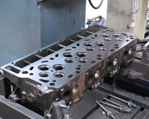
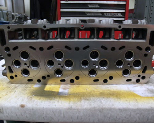
ENGINE PREP
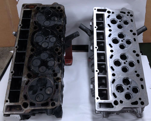
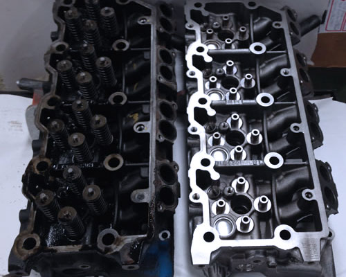
When your head arrives at UCF, we completely dismantle the heads for thorough cleaning. Heads and components go through our caustic acid jetwash and shot blast machine. At this point we give them a visual inspection for any unserviceable issues. Heads normally show some signs of head gasket leakage between the 2nd and 3rd cylinders which will be machined later to correct any problems.
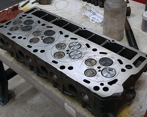
MAGNAFLUXING
Now we magnaflux and pressure test the cylinder heads to determine how many cracks need to be repaired and if there would be any defects that would render the head unrepairable.
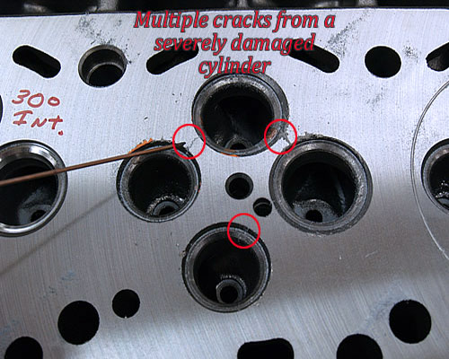
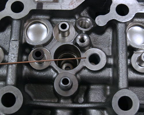
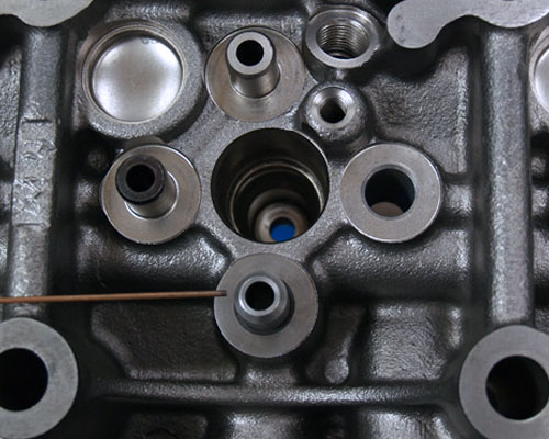
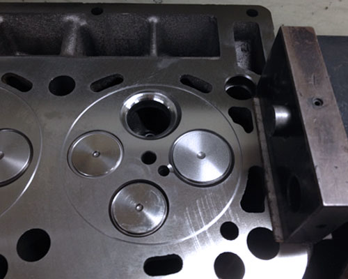
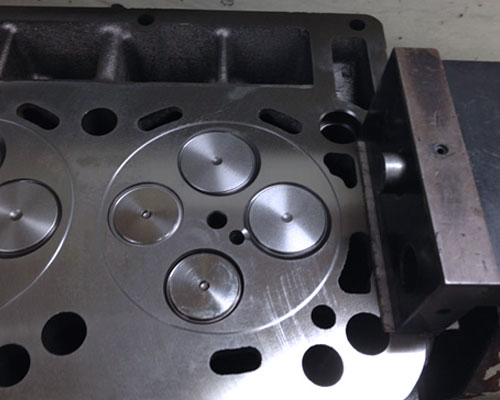
Pictured below is the result of the demo-head being dry-magnafluxed to show any cracks. The first picture shows a crack on the actual seat of the exhaust valve. In our second picture, there is a crack between the 2 intake seats.
The third picture is from a middle cylinder that has been severely damaged from either a bad injector or a blown head gasket. A defect this severe cannot be repaired.
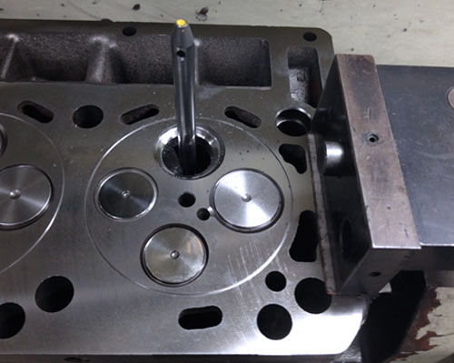
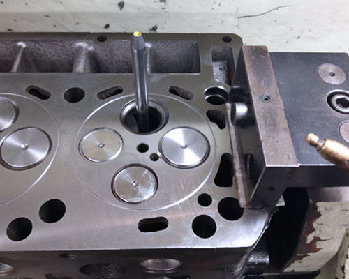
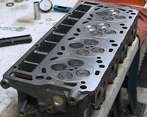
TESTING-VALVE GUIDES & SPRINGS
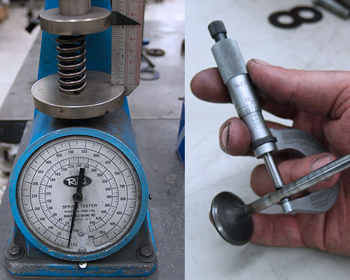 We check the valve guides for wear, measure valve stems for wear and test valve springs for spring force and pressure.
MACHINE VALVE GUIDE
We machine the valve guide to accept a new oil retention replacement valve guide. Below are different steps in the process of the new valve guide installation. More views of the process are found in tabs 4-b and 4-c.
VALVE GUIDE - TOP VIEW
 This is the top side of the head with the original guide bored out.
VALVE GUIDE - INSTALLED
The new guide is installed.
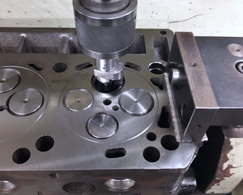
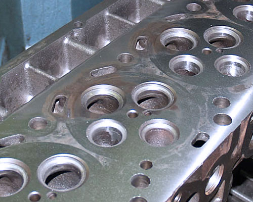
EXHAUST VALVE SEATS
We machine the cylinder heads to accept new hardened valve seat inserts. The exhaust valve seat is cut out to have a new valve seat insert installed.
INTAKE VALVE SEATS
The intake valve seat is cut out and a new seat is inserted. This picture has the seat insert already installed.
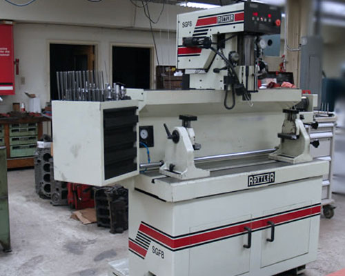
VALVE JOB
We perform a valve job using our new Rottler® SFG-8 precision multiple-angle Cylinder Head Center. This process assures a very accurate valve-to-seat alignment. Along with this process, we set the proper valve recession and stem height which is very important for optimum performance and longevity.
The heads being cut in these pictures are from a 4.0L Jeep 12-valve head. We will have shots from a Ford job soon.
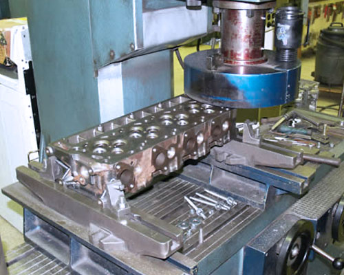
MACHINE CYLINDER HEAD
We machine the fire deck of the cylinder head with our Precision CBN resurfacing mill. This creates the proper RA finish for the M.L.S style gasket used in these engines.
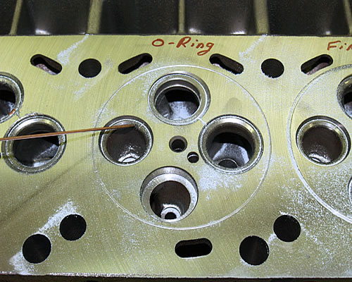
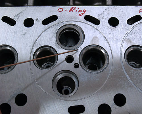
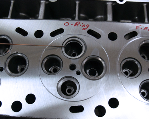
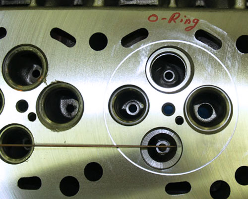
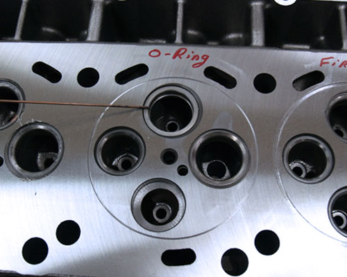
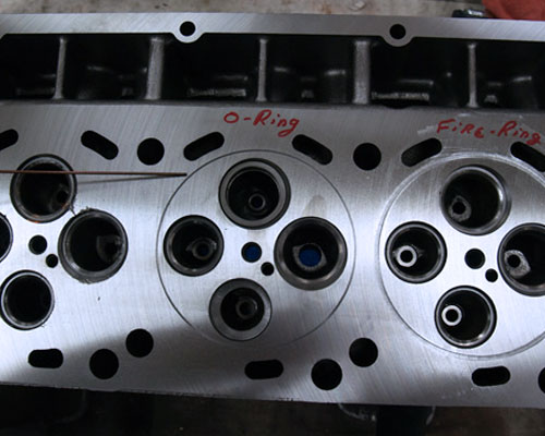
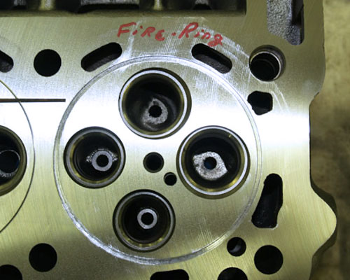
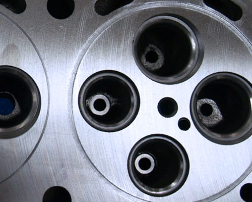
MACHINE RECEIVER-GROOVES FOR O-RINGS AND FIRE-RINGS
We machine the head with receiver grooves. The grooved cylinder on the left has been cut for an O-Ring; the one on the right a Fire Ring.
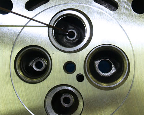
While not as common in the 6L Ford, it is possible to install Fire-Rings in a 6L head. The cylinder on the right has been square-cut for a Fire-Ring for demonstration purposes. Rather than a square bit, we always use a bit matching the curve of the installed Fire-Ring. This way the Fire-Ring sits precisely in a matched groove.
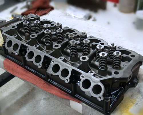
CLEANING & FINAL ASSEMBLY
- The head goes through a final cleaning process now that all machining is complete.
- We assemble the cylinder heads with new valve seals and install our custom-fit O-Ring wire or Fire-Rings.
- The head is placed on the bench for final inspection. Once it passes final inspection the head is painted with high-temperature corrosion resistant paint and packed for shipping/delivery.
Contact Us For a Quote
Call: (717) 249-8517 Email: ucfcontact@ucfmachineshop.com